Overview
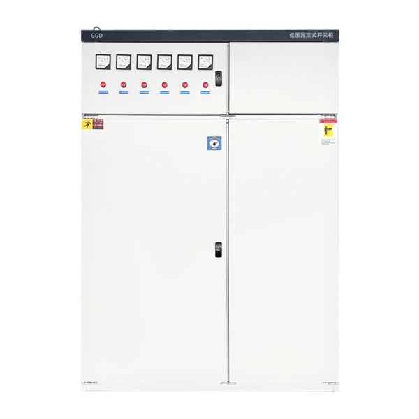
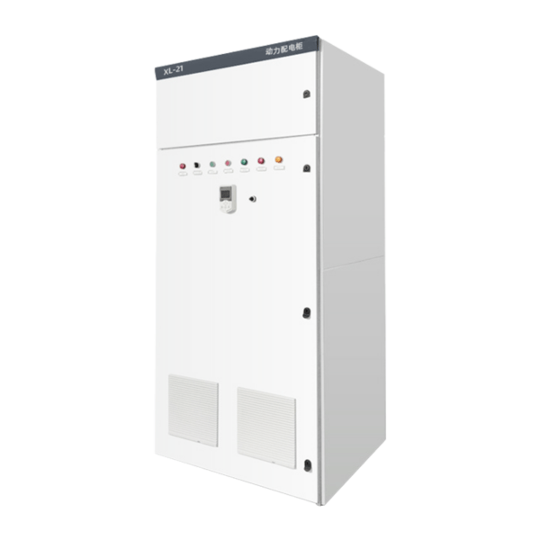
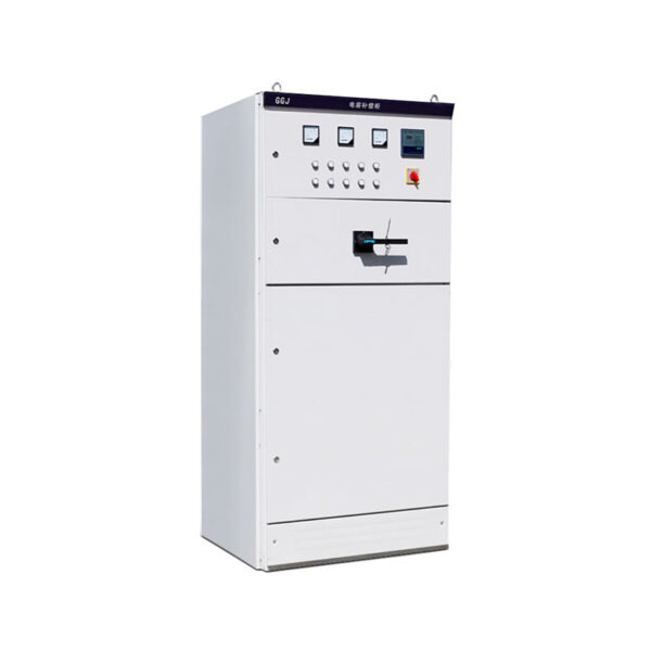
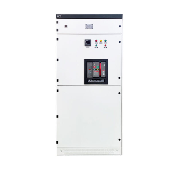
GCK low-voltage withdrawable switchgear is composed of a power distribution center (PC) cabinet and a motor control center (MCC). It is suitable for power plants, Power users such as substations, industrial and mining enterprises are used as power distribution systems with AC 50Hz, maximum working voltage to 66OV, and maximum working current to 3150A It is used for power conversion and distribution control of power distribution equipment such as power distribution, motor control, and lighting.
Operating Conditions
1. Altitude: ≤2000m;
2. The surrounding air temperature shall not be higher than +40°C, with a 24-hour average not exceeding +35°C, and not lower than -50°C;
3. Atmospheric conditions: Ambient air should be clean. The relative humidity shall not exceed 50% at +40°C, and higher humidity is allowed at lower temperatures, such as 90% at +20°C;
4. Installation location: A location free of fire and explosion risks, heavy dust or pollution, chemical corrosive substances, and intense mechanical vibration;
5. The inclination with respect to the vertical plane shall not exceed 5°.
If the above operating conditions are not satisfied, the user shall inform our company when placing the order, so that appropriate arrangements can be made through mutual consultation.
Technical Specification
| Item | Unit | Parameter | |
| Rated Operating Frequency | Hz | 50 | |
| Rated Operating Voltage | V | 380 / 660 | |
| Rated Operating Current | Horizontal Bus | A | 630-3150 |
| Vertical Bus | 600 | ||
| Rated Short-time Withstand Current | Horizontal Bus | kA/s | 80 |
| Vertical Bus | 50 | ||
| Rated Peak Withstand Current | Horizontal Bus | kA/0.1s | 176 |
| Vertical Bus | 110 | ||
| Main Circuit Connector | A | 200 / 400 | |
| Auxiliary Circuit Connector | 10 | ||
| 1min Power Frequency Withstand Voltage | V | 2500 | |
| Protection Class | / | IP40 | |
| Mode of Operation | / | In-place, remote, automatic | |
External Dimensions
Figure 1.Dimensional drawing
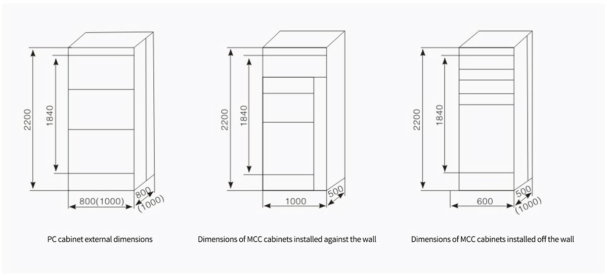
Figure 2.Installation dimensions and mounting holes
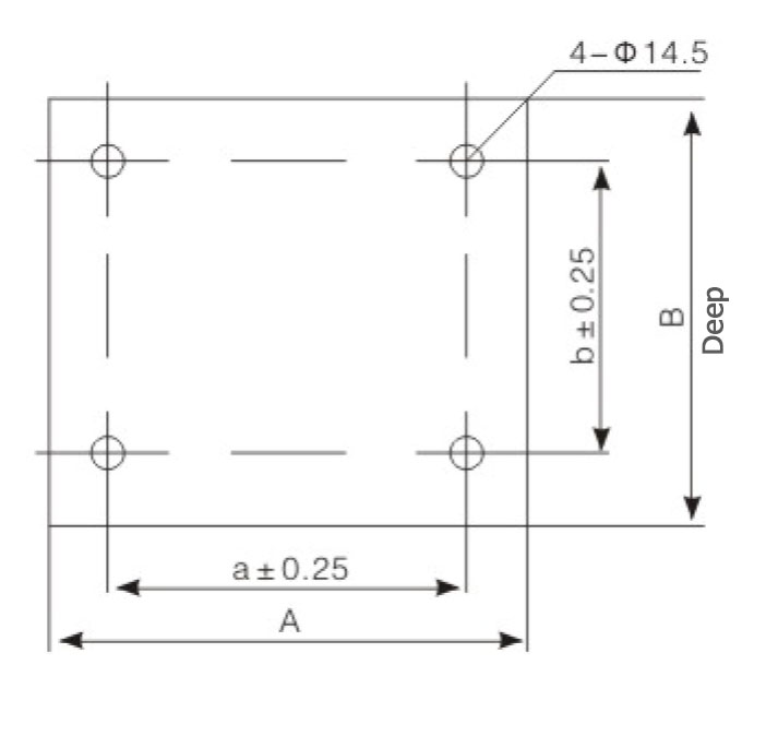
| Cabinet Width(A) | Cabinet Width(B) | Mounting Hole Spacing(a) | Mounting Hole Spacing(b) |
| 800 | 800 | 685 | 385 |
| 600 | 600 | 485 | 685 |
| 600 | 600 | 485 | 885 |
| 800 | 800 | 685 | 685 |
| 800 | 800 | 685 | 885 |
| 1000 | 1000 | 885 | 685 |
| 1000 | 1000 | 885 | 885 |