Overview
KYN28-12 withdrawable metal-clad switchgear is suitable for 3.6-12kV three-phase AC 50Hz power grid, used to receive and distribute electric energy, control, monitor and protect circuits. It can be used for single bus, single bus segment system or double bus system. The switchgear complies with IEC298 “AC metal-clad switchgear and control equipment with rated voltage above 1kV and below 52kV”, IEC694 “Common terms for high-voltage switches and con-trol equipment”, China’s GB3906 (3-35kV AC metal-enclosed switchgear ) and DIA04 “Ordering conditions for indoor AC high-voltage switchgear”, Germany DIN.VDE0670 “AC switchgear with rated voltage above 1kV” and other standards, and has a complete and reliable anti-misoperation function.
Operating Conditions
1. Ambient temperature: -10℃ ~+40℃;
2. Altitude: 1000m;
3. Relative humidity: daily average 95%, monthly average 90%;
4. Seismic resistance: 8 magnitude.
5. Occasions without flammable and explosive matter, without corrosive chemical and frequent severe vibration, without strong shake.
Technical Specification
| Item | Unit | Data | |
| Rated voltage | KV | 3/6/7.2/12 | |
| Rated frequency | Hz | 50 | |
| Rated current(circuit breaker) | A | 630, 1250, 1600, 2000, 2500, 3150 | |
| Rated current(switchgear) | A | 630, 1250, 1600, 2000, 2500, 3150 | |
| Rated short-time withstand current (4s) | KA | 16, 20, 25, 31.5, 40, 50 | |
| Rated peak withstand current※ | KA | 40, 50, 63, 80, 100, 125 | |
| Rated short-circuit breaking current | KA | 16, 20, 25, 31.5, 40, 50 | |
| Rated short-circuit making current※ | KA | 40, 50, 63, 80, 100, 125 | |
| Rated insulation level | 1min.P.F. withstand voltage (phases to ground/gaps) | KV | 24/32/42 |
| Lightning impulse withstand voltage (phases to ground/gaps) | KV | 40/60/75 | |
| Protection class | Enclosure: IP4X, IP2X (VCB Door opened) | ||
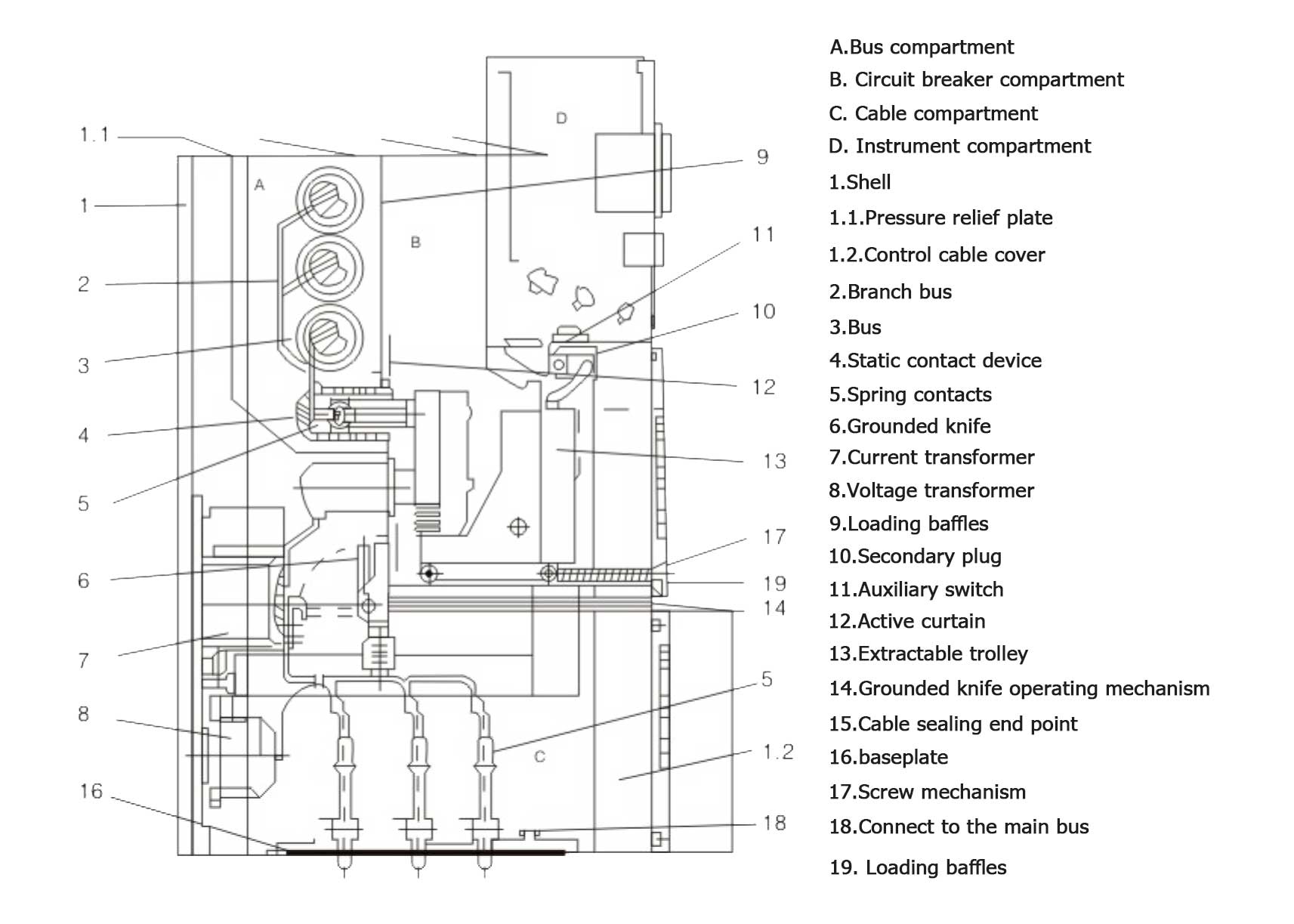
Basic Structure Diagram of Switchgear
Installation of Switchgear
- According to the project requirements and the drawings, transport the switch cabinet to a specific location. For example, if a row of long switch cabinets (such as more than 10 units) is arranged, the cabi-net assembly work should start from the middle.
- Use specific transportation tools such as cranes or forklifts. It is strictly forbidden to use rollers and crowbars.
- Pull out the circuit breaker trolley from the switch cabinet and store it somewhere else for safekeeping.
- Loosen the fixing bolts in front of the busbar compartment and remove the vertical par-tition 9.
- Loosen the fixing bolts of the horizontal partition 19 under the circuit breaker compartment and remove the horizontal partition.
- Loosen and remove the bottom plate 16.
- Remove the cover plates 1 and 2 from the control wire duct on the left side of the switch cabinet. The cover plate of the control wire duct on the right front should be removed at the same time.
- Install the switch cabinets one by one on the foundation, including horizontal and vertical aspects. The unevenness of the switch cabinet installation shall not exceed 2mm.
- When the switch cabinet is completely assembled (spliced), it can be connected to the foundation channel steel with anchor screws or welded to the foundation channel steel with electric welding.and technical measures.