
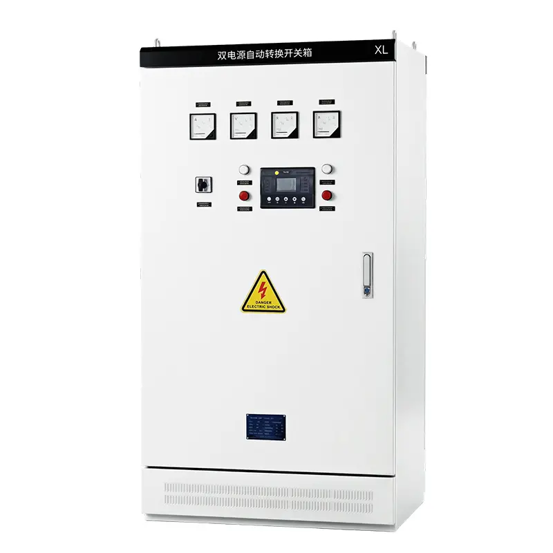
ATS Automatic Transfer Switch Cabinet
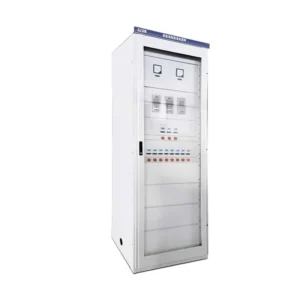
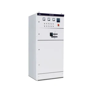
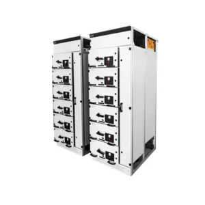
The ATS Dual Power Supply Automatic Transfer Switch Cabinet is a low-voltage (0.4 kV) switchgear assembly designed for automatic transfer between two independent power sources. Its core component is an Automatic Transfer Switch (ATS).
The cabinet is connected to two independent power supplies. When the main power supply experiences a voltage loss, phase failure, overvoltage, or undervoltage, the ATS automatically transfers the load to the standby power supply, ensuring continuity of power to downstream loads.
The system is equipped with both mechanical and electrical interlocks to prevent the two power sources from being connected in parallel simultaneously, thereby eliminating the risk of a short circuit caused by simultaneous closing of both power sources.
Get a QuoteOverview
The ATS Automatic Transfer Switch Cabinet is a low-voltage power distribution solution designed to transfer electrical loads between two independent power sources. Rated at 400V AC, it is equipped with an automatic transfer switch (ATS) that monitors the incoming power supply and switches to the standby source when the main supply fails or falls outside preset voltage limits.
With mechanical and electrical interlocking, the cabinet helps prevent both power sources from being connected simultaneously. It is suitable for commercial buildings, industrial facilities, backup generator systems, and other applications where a reliable power supply is essential.
The cabinet can be customized according to rated current, number of poles, transfer switch type, enclosure protection rating, and control requirements.
Model and Configuration
The model designation identifies the cabinet structure, transfer function, rated current, pole configuration, and ATS switching class. A typical configuration may include the following:
- GGD: Standard low-voltage switchgear cabinet enclosure.
- ATS: Automatic transfer switching function.
- 400: Rated current of 400A.
- 4P: Four-pole configuration for three-phase, four-wire systems. A 3P configuration is used for three-phase, three-wire systems where applicable.
- PC: Class PC automatic transfer switching equipment.
- CB: Class CB automatic transfer switching equipment.
The exact model designation depends on the manufacturer’s coding system and the selected configuration. XL21 enclosures may also be used for certain smaller distribution cabinet designs.
PC-Class vs. CB-Class ATS Cabinet
ATS cabinets are available in PC-class and CB-class configurations. The main difference is the switching device structure and its short-circuit operating capability.
PC-Class ATS Cabinet
A PC-class ATS uses a dedicated transfer switching device designed to carry and transfer load current and withstand specified short-circuit currents. It is commonly selected for applications requiring high switching reliability and compact construction.
Key features:
- Integrated transfer switching mechanism
- Mechanical and electrical interlocking
- High short-circuit withstand capability, subject to the device rating
- Suitable for critical power supply systems when specified and certified for the application
Typical applications include fire pumps, smoke exhaust fans, elevators, hospitals, data centers, and high-rise buildings.
CB-Class ATS Cabinet
A CB-class ATS typically uses two interlocked circuit breakers to transfer the load between power sources. The circuit breakers provide overcurrent protection and are selected according to the system’s load and short-circuit requirements.
Key features:
- Two circuit breakers with an interlocking mechanism
- Integrated switching and overcurrent protection functions
- Flexible protection settings, depending on the selected breakers
- A practical solution for general low-voltage power distribution
Typical applications include warehouse lighting, commercial premises, general ventilation systems, and other non-critical loads.
The appropriate class should be selected according to the load characteristics, fault levels, protection coordination, and applicable project requirements.
Internal Structure of the ATS Cabinet
The cabinet can be arranged into separate functional compartments to support safe operation, maintenance, and cable management.
1. Incoming Power Compartment
Accommodates the main and standby power incoming connections, copper busbars, and incoming circuit protection devices.
2. ATS Switching Compartment
Contains the automatic transfer switch, switching mechanism, current transformers where required, and mechanical interlocking components.
3. Outgoing Cable Compartment
Provides outgoing busbar connections, load terminals, PE protective earthing busbar, and cable termination space.
4. Control and Instrumentation Compartment
Houses the ATS controller, power indicator lights, audible alarm, operating buttons, monitoring instruments, and fire alarm interface terminals where specified.
Optional accessories include a manual operating handle, anti-condensation heater, inspection window, and pressure-relief cover, subject to the cabinet design.
Technical Specifications
Typical ratings and configuration options are listed below. Final specifications depend on the selected components and project requirements.
| Parameter | Specification |
| Product type | ATS Automatic Transfer Switch Cabinet |
| Rated operational voltage | 400V AC |
| Control voltage | AC 220V / DC 24V, as specified |
| Rated frequency | 50Hz |
| Rated current | 63A, 100A, 160A, 250A, 400A, 630A, 1000A, 1600A |
| Number of poles | 3P / 4P |
| ATS class | PC-class / CB-class |
| Enclosure protection | IP30 for typical indoor configurations; IP54 options available |
| Enclosure material | Painted steel; stainless steel options available |
| Transfer delay | Adjustable, typically 0.1–30 seconds, depending on the controller |
| Short-circuit performance | Selected according to the ATS rating and system fault level |
| Operating modes | Automatic / Manual |
| Optional functions | Generator start/stop interface, fire alarm interface, RS-485 communication, remote monitoring |
The short-circuit withstand rating, transfer time, enclosure protection, and operating temperature range must be confirmed against the selected equipment and approved technical drawings.
ATS Operating Modes
Automatic Mode
In automatic mode, the controller monitors both power sources. When the main supply fails or exceeds the configured voltage limits, the ATS transfers the load to the standby source according to the programmed logic and time delays. Once the main supply returns to an acceptable condition, the system can automatically transfer the load back, if the return function is enabled.
Manual Mode
Manual operation allows authorized personnel to operate the transfer switch during commissioning, testing, or maintenance, in accordance with the manufacturer’s operating procedures.
OFF or Isolation Position
Where the selected ATS provides a suitable OFF or isolation position, both sources can be disconnected from the load for maintenance. The isolation procedure must follow the equipment design and applicable electrical safety requirements.
Key Features and Benefits
- Automatic power transfer: Transfers loads between the main and standby power sources when configured supply fault conditions occur.
- Interlocking protection: Mechanical and electrical interlocks help prevent simultaneous connection of the two sources.
- Power supply monitoring: Detects configured voltage abnormalities and phase failures when supported by the controller.
- Generator integration: Optional interfaces support generator start/stop control and utility-generator transfer applications.
- Remote monitoring: RS-485 communication and other monitoring options are available for compatible control systems.
- Flexible configuration: Rated current, pole arrangement, ATS class, enclosure material, and protection rating can be selected for different installations.
Applications of ATS Automatic Transfer Switch Cabinets
ATS cabinets are used in low-voltage power distribution systems where loads require an alternative power source.
Common applications include:
- Commercial buildings and high-rise buildings
- Hospitals and healthcare facilities
- Data centers and communication rooms
- Fire pumps and smoke control systems
- Elevators and building services
- Industrial production lines
- Water and wastewater treatment facilities
- Warehouses, retail premises, and commercial lighting
- Utility-to-generator and generator-to-generator power systems
For fire protection and other life-safety applications, the ATS configuration must meet the applicable local codes, project specifications, and certification requirements.
ATS Cabinet vs. No-Break Transfer Cabinet
A conventional ATS generally uses open-transition switching, in which the load is disconnected from one source before being connected to the other. A brief interruption may occur during the transfer process.
A no-break or seamless transfer solution requires additional technology and suitable source conditions to minimize or eliminate the interruption. Depending on the design, this may involve source synchronization, a static transfer switch, or another specialized transfer arrangement.
For sensitive equipment such as servers, data processing systems, and certain variable-frequency-drive applications, the transfer method should be selected according to the load’s tolerance for power interruption. A zero-interruption claim should only be made when supported by the actual system design and performance specifications.
Standard Operating Environment
The following are typical design conditions and should be confirmed for the final product:
- Ambient temperature: -15°C to +40°C
- Installation altitude: Up to 1,000m without altitude-related derating, subject to component specifications
- Relative humidity: Daily average up to 95%, provided condensation does not occur and the equipment is rated for the conditions
- Installation environment: Free from corrosive gases, explosive dust, and severe vibration
Outdoor installations, humid basements, high-altitude sites, and other demanding environments may require additional protection or customized enclosure designs.
How to Select and Order an ATS Cabinet
To select the appropriate ATS cabinet, please provide the following information:
- Electrical ratings: Rated current, system voltage, frequency, and 3P or 4P configuration.
- ATS class: PC-class or CB-class, based on the application and protection requirements.
- Power sources: Utility-to-utility, utility-to-generator, or generator-to-generator.
- Application: Fire protection, critical loads, industrial equipment, commercial lighting, or general power distribution.
- Control functions: Automatic return, transfer delay, generator start/stop, fire alarm interface, metering, and remote communication.
- Cabinet requirements: Indoor or outdoor installation, IP rating, enclosure material, and cable entry/exit arrangement.
- Site conditions: Ambient temperature, humidity, altitude, and any special environmental requirements.
Our ATS cabinet configurations can be selected according to your electrical system requirements and project specifications.
Contact us with your rated current, ATS class, power source arrangement, and application details to obtain a suitable configuration and quotation.